How to create an operation system from scratch
I always wanted to understand how computers boot into the linux kernel.
In this post, I will summorize all of my knowledge that I collected.
This post is targeted torward advanced users, those who studied computer science or has a background. And also people who researched about OS development. Here it is summorized easily.
Before we start, let me list the most useful resources for OS development:
- OSDev.org wikipedia
- Writing a Simple Operating System — from Scratch by Nick Blundell
- BIOS Interrupts and Functions
- YouTube video: Protected mode, explains in detail
The post is written sequentially, which means it is recommended to read it from top to bottom. The progress is made in the same order as the post, so you can see me actually struggle and get back to previous points.
Boot process
The first step is to understand how the computer reaches our kernel code from BIOS.
After POST occurs, which checks that the hardware works correctly, the BIOS starts the bootloader.
It looks for each bootable device (disk, floppy drive, cd rom). For each of the storage media is looks for sector 1 (first sector).
In sector 1 of the boot device, if the last 2 bytes are the magic bytes 0xAA55 then the device can be booted.
This is caled Master Boot Record (MBR), thats how the BIOS knows if it should boot from that device. Today we use UEFI, but its not important, since MBR is simpler and I’ll use it instead.
Note: the BIOS looks for each device in predefined order in the BIOS menu (boot order).
The first 510 bytes of sector 1 are the assembly code. This assembly code will be interacting with BIOS interrupts.
Run assembly code in bootloader
Basic code that does nothing:
ORG 0x7c00
BITS 16

jmp $

times 510-($ - $$) db 0
dw 0xAA55
The last 2 bytes are the magic 0x55AA bytes
The first 510 bytes are the jmp $ instruction which jumps to the same line as current instruction (infinite loop).
And the rest of the bytes are zeros (jmp $ takes 3 bytes, so we are left with 510-3=507 bytes are zeros).
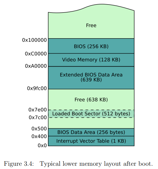
BITS 16 means we are running in real-mode, and ORG 0x7C00 is the offset from where we start. The BIOS always loads our bootsector onto address 0x7C00. The BIOS did hardware initialization and other checks, those required some memory. So to avoid our code to override the BIOS memory, it puts our code in predefined memory area 0x7C00 (in RAM).
We are working in 16-bits which means we can only use addresses up to 2 bytes long.
Notice that we are working in little-endian (default for most CPU architectures to use little-endian), and so 0xAA55 appears as last bytes like so: 55 AA.
Side note: big endian is used commonly in networking, I won’t go into the reason, but its primaraly performance (little-endian) and readability (big-endian).
Running the bootsector
To run the bootsector we can use QEMU which is an emulator that can run on any CPU architecture hosts that are different CPU architecture.
For example I can run x64 operation system in macOS M1 (which is arm64).
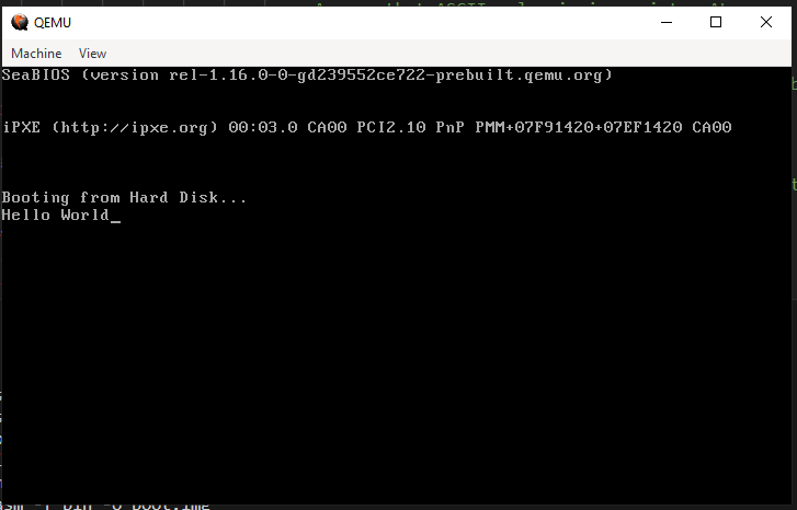
Here is screenshot showing running QEMU with the bootsector code below:
nasm bootsector.asm -f bin -o boot.img
qemu-system-x86_64 boot.img
Print ‘Hello World’ in assembly
Code:
[global Start]
[BITS 16]
[ORG 0x7C00]

section .text
Start:
    mov si, String                      ;Store string pointer to SI
    call PrintString                    ;Call print string procedure
    jmp $                               ;Infinite loop, hang it here.

PrintCharacter:                         ;Procedure to print character on screen
                                        ;Assume that ASCII value is in register AL
    mov ah, 0x0E                        ;Tell BIOS that we need to print one charater on screen.
    mov bh, 0x00                        ;Page no.
    mov bl, 0x07                        ;Text attribute 0x07 is lightgrey font on black background
    int 0x10                            ;Call video interrupt
    ret                                 ;Return to calling procedure
PrintString:                            ;Procedure to print string on screen
                                        ;Assume that string starting pointer is in register SI
    next_character:                     ;Lable to fetch next character from string
        mov al, [SI]                    ;Get a byte from string and store in AL register
        inc SI                          ;Increment SI pointer
        or AL, AL                       ;Check if value in AL is zero (end of string)
        jz exit_function                ;If end then return
        call PrintCharacter             ;Else print the character which is in AL register
        jmp next_character              ;Fetch next character from string
        exit_function:                  ;End label
        ret                             ;Return from procedure
String db 'Hello World', 0              ;HelloWorld string ending with 0

times 510 - ($ - $$) db 0               ;Fill the rest of sector with 0
dw 0xAA55                               ;Add boot signature at the end of bootloader
Here is the hexdump of the program:
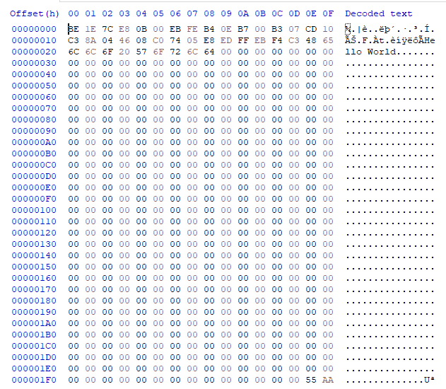
We can see ‘Hello World’ appears in the dump, aswell as the last 2 magic bytes.
We can continue to play with assembly and do whatever we want in assembly, but we want to load the kernel.
Understand CPU addressing
In 16-bit real-mode the CPU has 3 registers that are used for addressing:
CS- Code SegmentDS- Data SegmentSS- Stack Segment
You should read on the internet about them. Understand segments.
In a nutshell the addressing mode is called segment:offset:
We can access up to 1MB of effective address using segments. An effective address is computed by combining the base address from the segment register and the offset value. When we run mov ax, [0xffff] the CPU will take the value of DS and multiply it by 16 and add it to the address. So if DS is 0x1000, then the address will be 0x1000*16 + 0xffff.
Notice: 0xffff*16 + 0xffff = 0x10FFEF = 1,114,095 which is a little mode than 20 bits (2^10=1,048,576).
Understand Disk I/O - CHS - Cylinder, Head, Sector
When we talk about hard drives, to get desired memory block we need to know where to read from or write to.
This is where the CHS comes from. It specifies the cylinder, head and sector of the hard drive. Basically it is a 3D coordinate system.
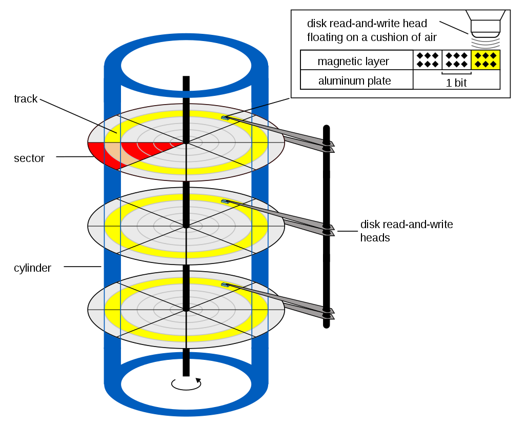
In a nutshell, cylinder is what physical platter we read from (in blue), head (or track) is the radius of the platter (in yellow), and sector is the angle of the platter (in red).
Initializing the stack
We need to initialize the stack, so when we use it, it wont override other memory. Remember: the stack grows downwards.
Since our code starts at 0x7C00, then if we initialize the stack pointer to 0x7C01, after one byte push the stack pointer will override 0x7C01, which is our code. We don’t want that.
So we need to initialize the stack pointer to a higher address, or lower address. If we do it higher than 0x7C00 we still have to worry about the stack growing downwards. But if we initialize it to a lower address (lower than 0x7C00), then it can’t override our code.
To summorize, we will initialize the stack pointer going downwards, so it won’t override our code:
mov bp, 0x7C00
mov sp, bp
Read from disk
Now we want to read different sectors of our code. Since 512 bytes isn’t enough, we will make a bootable image of 2 sectors (1024 bytes).
The first sector will be regular bootsector code, and the second sector will be filled with 0xFF bytes. The first sector will read 16 bytes of the second sector and print it to the screen.
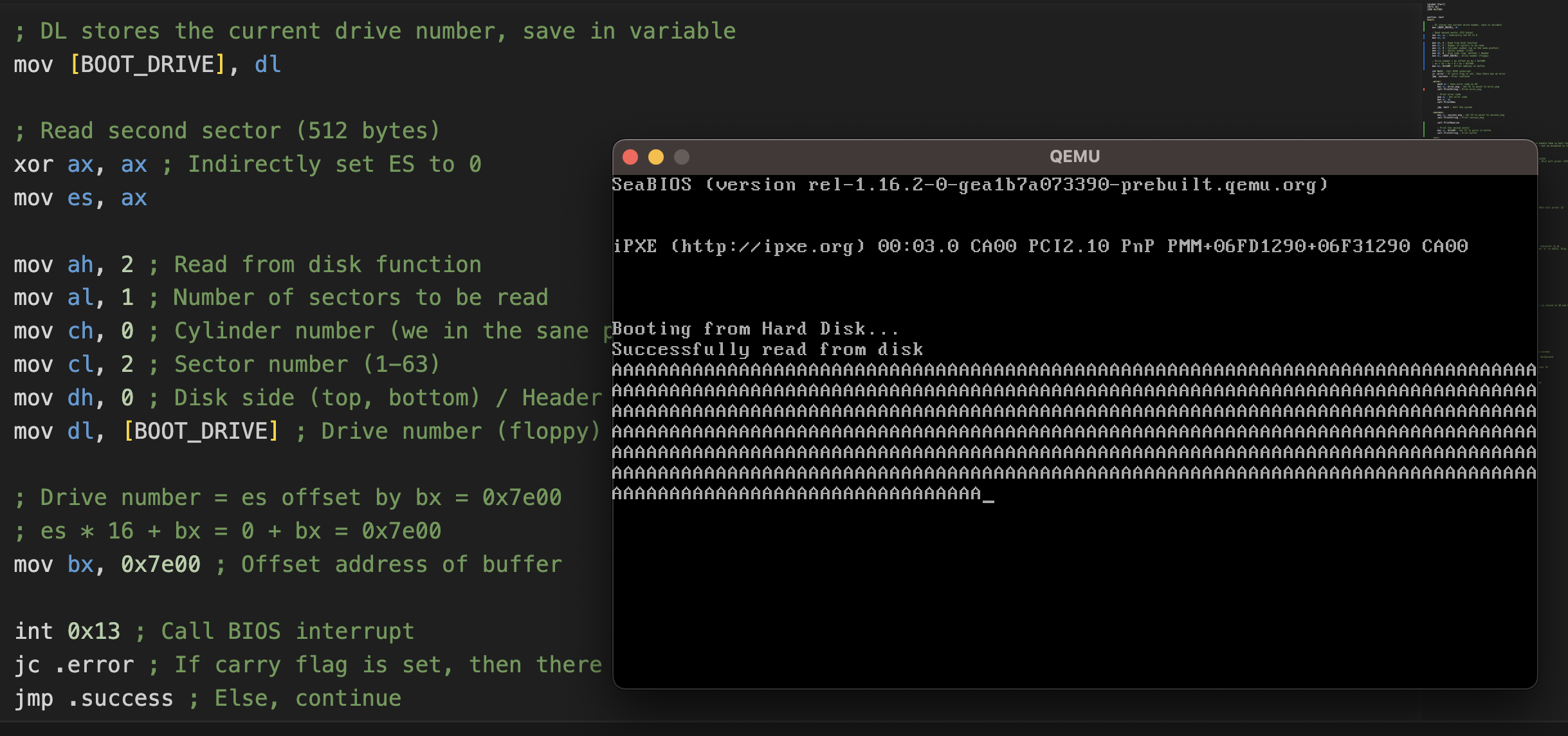
The picture above shows how to read the second sector. In the bootloader sector (first sector) we have the code to read the second sector.
The second sector is filled with ‘A’ bytes, and then we print it to the screen.
Note: the disk number is stored in DL register right after the BIOS loads the bootloader. We save it in a variable called BOOT_DRIVE.
The BIOS reads the sector into memory at location ES:BX (remember CPU addressing?). We set ES to 0, and BX to 0x7e00 as a dummy example.
The code:
[global Start]
[BITS 16]
[ORG 0x7C00]


section .text
Start:
    ; DL stores the current drive number, save in variable
    mov [BOOT_DRIVE], dl

    ; Initialize the stack
    mov bp, 0x7C00
    mov sp, bp

    ; Read second sector (512 bytes)
    xor ax, ax ; Indirectly set ES to 0
    mov es, ax

    mov ah, 2 ; Read from disk function
    mov al, 1 ; Number of sectors to be read
    mov ch, 0 ; Cylinder number (we in the sane platter)
    mov cl, 2 ; Sector number (1-63)
    mov dh, 0 ; Disk side (top, bottom) / Header
    mov dl, [BOOT_DRIVE] ; Drive number (floppy)

    ; Drive number = es offset by bx = 0x7e00
    ; es * 16 + bx = 0 + bx = 0x7e00
    mov bx, 0x7e00 ; Offset address of buffer

    int 0x13 ; Call BIOS interrupt
    jc .error ; If carry flag is set, then there was an error
    jmp .success ; Else, continue

    .error:
        push ax ; Save error code in AH
        mov si, error_msg ; Set SI to point to error_msg
        call PrintString ; Print error_msg

        ; Print error code
        pop ax ; Get error code
        mov al, ah
        call Print2Hex

        jmp .halt ; Halt the system

    .success:
        mov si, success_msg ; Set SI to point to success_msg
        call PrintString ; Print success_msg

        call PrintNewLine

        ; Print the second sector
        mov si, 0x7e00 ; Set SI to point to buffer
        call PrintString ; Print buffer

    .halt:
        ; End
        ;jmp EnterProtectedMode
        cli                                 ;Clear all interrupts, so we don't need to handle them in halt state
        hlt                                 ;Halt the system - wait for next interrupt - but we disabled so its very efficient and not using much CPU%

Print4Hex:
    ; Input AX register, BL register (optional)
    ; Output: None
    ; Prints the hex value of AX register (4 nibbles). Example: AX=0x1234 will print: 0x1234
    ; If you want to print prefix '0x' then set BL=0, else set BL=1. Example: AX=0x1234, BL=1 will print: 1234
    push ax

    shr ax, 8
    mov ah, bl ; Print prefix according to BL input for first byte
    call Print2Hex

    ; Print low byte
    pop ax
    mov ah, 1 ; Here we don't need to print prefix
    call Print2Hex

    ret

Print2Hex:
    ; Input: AL register, AH register (optional)
    ; Output: None
    ; Print the hex value of AL register (2 nibbles). Example: AL=0x12 will print: 0x12
    ; If you want to print prefix '0x' then set AH=0, else set AH=1. Example: AL=0x12, AH=1 will print: 12
    cmp ah, 1
    je .no_prefix
    ; Print hex prefix
    push ax
    mov al, '0'
    call PrintCharacter
    mov al, 'x'
    call PrintCharacter
    pop ax ; Get the argument
    .no_prefix:

    ; Print high nibble
    call ALToHex
    push ax ; Store for low nibble printing later on
    mov al, ah ; Move high nibble to AL, since the PrintCharacter procedure expects the character in AL
    ; Check if nibble is greater than 0x9. If it does, then we need offset of 0x41 to get 'A' in ASCII. Else, we need offset of 0x30 to get '0' in ASCII.
    cmp al, 0xA
    jl .finish
    add al, 0x7
    .finish:
    add al, 0x30
    call PrintCharacter

    ; Print low nibble
    pop ax
    cmp al, 0xA
    jl .finish2
    add al, 0x7
    .finish2:
    add al, 0x30
    call PrintCharacter

    ret

ALToHex:
    ; Input: AL register
    ; Output: AX register
    ; Convert a number in AL to hex nibbles. Example: 256 -> 0xAB. The high nibble (0xA) is stored in AH and the low nibble (0xB) in AL
    push ax ; Save AL
    ; Get high nibble of AL, store in DH for later retrieval
    and al, 0xF0
    shr al, 4
    mov dh, al

    pop ax
    ; Get low nibble of AL, store in AL
    and al, 0x0F

    mov ah, dh ; Retrieve high nibble from DH to AH
    ret


PrintCharacter:                         ;Procedure to print character on screen
                                        ;Assume that ASCII value is in register AL
    mov ah, 0x0E                        ;Tell BIOS that we need to print one charater on screen.
    mov bh, 0x00                        ;Page no.
    mov bl, 0x07                        ;Text attribute 0x07 is lightgrey font on black background
    int 0x10                            ;Call video interrupt
    ret                                 ;Return to calling procedure
PrintString:                            ;Procedure to print string on screen
                                        ;Assume that string starting pointer is in register SI
    .next_character:                     ;Lable to fetch next character from string
        mov al, [SI]                    ;Get a byte from string and store in AL register
        inc SI                          ;Increment SI pointer
        or AL, AL                       ;Check if value in AL is zero (end of string)
        jz .exit_function                ;If end then return
        call PrintCharacter             ;Else print the character which is in AL register
        jmp .next_character              ;Fetch next character from string
        .exit_function:                  ;End label
        ret                             ;Return from procedure
PrintNewLine:
    ; Print new line
    mov al, 0x0D
    call PrintCharacter
    mov al, 0x0A
    call PrintCharacter
    ret

; CODE_SEG equ code_descriptor - GDT_Start
; DATA_SEG equ data_descriptor - GDT_Start
BOOT_DRIVE db 0
error_msg db 'Error reading from disk, error code: ', 0
success_msg db 'Successfully read from disk', 0

times 510 - ($ - $$) db 0               ;Fill the rest of sector with 0
dw 0xAA55                               ;Add boot signature at the end of bootloader

; Second sector is filled with 'A'
times 512 db 'A'
Note: the BIOS stops reading when it reaches 0x00 (zero terminated string).
So it was luck that after the second sector, the next bytes are zero. We should never do that again, since its not safe.
Understand the stack: SP, BP, SS
The stack is used for when we push or pop values. It grows from high address to low address. It grows downwards.
When we push a value, the stack pointer SP is decremented by the amount of bytes of the value.
When we pop a value, the stack pointer SP is incremented by the amount of bytes of the value, and the value is stored inside a register.
The SP points to the top element of the stack (last element pushed).
Now we have 2 more registers to talk about:
BP- Base PointerSS- Stack Segment
The BP register is like the stack frame. It points to the start (base) of the current stack frame. Stack frame is a block of memory when usually when we call a function. The stack frame is used to store local variables, and other data in the current local scope.
So the BP points to the current stack frame. It is used to debug the current stack frame for each stack frame, so its used extensively in debugging.
We can calculate how much bytes a function used the stack by subtracting BP from SP.
Lastly, the SS register is the stack segment. It is used to tell the CPU where the stack is located in memory (beginning of the entire stack, where it begins). It is used with the SP register to calculate the effective address of the stack. It is used in combination with SP to reach high effective address, more than a single register can hold (more than 2 bytes).
For example of SS = 0xAAAA and SP = 0x0001, then the effective address of the top of stack is 0xAAAA*16 + 0x0001 = 0xAAAA0 + 0x0001 = 0xAAAA1.
Here is an image describing the stack:
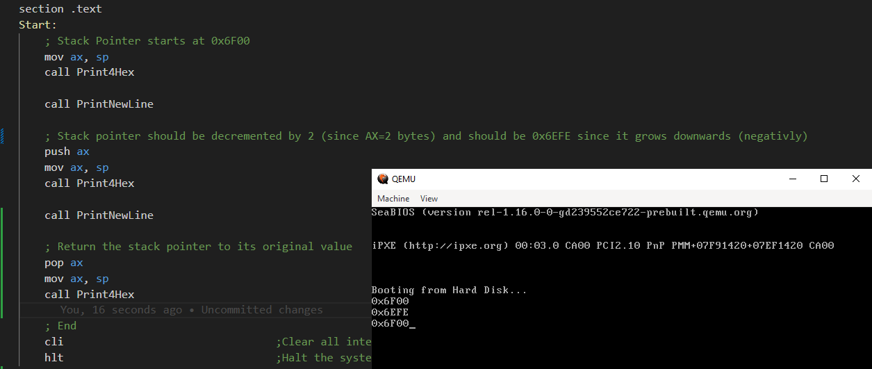
This is my code. It first prints the value of SP register (0x6F00)
Then it pushes AX onto stack, which should decrement SP by 2, and we get 0x6EFE;
Then it pops back AX from the stack, which should increment SP by 2, and we get 0x6F00 again.
Write assembly in 2 files instead of 1
So far we written the assembly code in 1 file. We need to understand how to write code in 2 files so its easier to debug and write code.
The bootsector should not change. The size of the bootsector is still 512 bytes.
However now we want to add a second sector filled with ‘A’ characters. The bootsector will read the second sector and print it.
second_sector.asm:
times 512 db 'A'Now we combine seperatly the bootsector and the second sector:
nasm bootsector.asm -o bootsector.bin
nasm second_sector.asm -o second_sector.bin
cat bootsector.bin second_sector.bin > boot.img
qemu-system-x86_64 boot.img
Include files in assembly
Instead of combining two assembly files like I did above with calling the compiler twice we can use the compiler once.
bootsector.asm:
...

%include "second_sector.asm"
Now we can just compile:
nasm -f bin bootsector.asm -o boot.img
qemu-system-x86_64 boot.img
Entering 32-bit protected mode
We want to switch 16-bit real-mode to 32-bit protected mode. To make it short, the reason is that it gives us more features, and we can use more memory. As the name suggests - it protects the memory from being accessed by different segments.
We need to understand GDT (Global Descriptor Table) and IDT (Interrupt Descriptor Table) to understand protected mode.
In 32-bit protected mode we can’t call BIOS interrupts anymore. So how do we display something on the screen? In VGA mode we simply need to write to the memory location 0xB8000 and it will display on the screen. But in protected mode we can’t do that, because we can’t access memory directly. We need to use the GDT to access memory.
To enter protected mode:
- Disable interrupts (
cli) - Load the GDT (
lgdt [GDT_Descriptor]-lgdtis a new instruction we never seen before) - Enable A20 line (set last bit of
cr0register to 1, this is a new register we never seen before)
Step 1 and 3 is easy. I’ll talk about step 2 in the next section.
Understand GDT (Global Descriptor Table)
We need to define the GDT in order to enter protected mode. The GDT will sit inside the bootsector code.
Here are some of the resources I learned from:
The Global Descriptor Table (GDT) is a system-wide data structure used in x86 protected mode to define and manage memory segments. It is a table of segment descriptors that describe the attributes and properties of various memory segments used by the processor.
The GDT holds multiple segments entries. GDT is a descriptor (list of properties) which describe the segments.
GDT must contain:
- Code Segment Descriptor
- Data Segment Descriptor
Segment Descriptor Structure
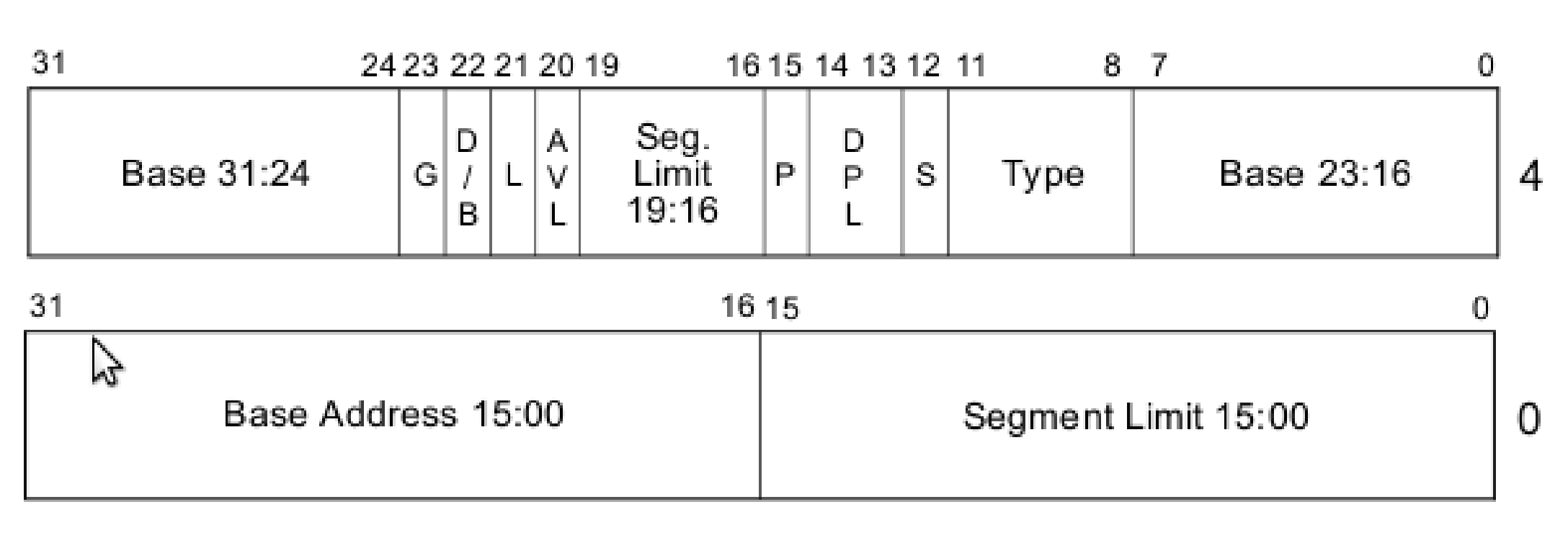
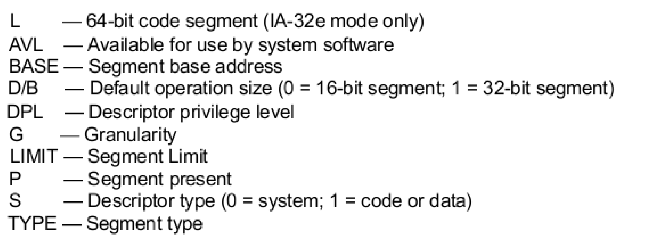
Both the code segment and data segment have almost the same structure as in the above image.
In the next section it will be made more clearer.
Code Segment Descriptor
It describes the code segment.
Attributes / Properties:
- Size (of the segment). It consists of:
- Base [32 bits] (the start location of the segment)
- Limit [20 bits] (describes the size of the segment)
- Present [1 bit] (1 - if the segment is used, 0 - if the segment is not used)
- Privilege [2 bits] (Describes segment privilege level, implements memory protection / access permissions. 0 - highest privilege, 11 - lowest privilege)
- Type [1 bit] (1 - if code OR data segment)
- Type flags [4 bits]
- Bit 3: Executable? (1 - if executable, 0 - if not executable)
- Bit 2: Conforming (can this be executed by lower privilege level?) (1 - this segment can be accessed by lower privilege level, 0 - this segment can’t be accessed by lower privilege level)
- Bit 1: Readable? (1 - if readable, 0 - if not readable)
- Bit 0: Accessed? (managed by the CPU, don’t touch. 1 - if accessed, 0 - if not accessed)
- Other flags [4 bits]
- Bit 3: Granularity? (If set, limit is multiplied by 4KB (0x1000), else limit is in bytes)
- Bit 2: Size (If set, 32-bit protected mode, else 16-bit protected mode)
- Bit 1: Reserved (0)
- Bit 0: Reserved (0)
Now we decide how to build our OS.
In short, I will go with flat-memory model (not segmentation and not paging).
I will also run in ring-0 (highest privilege level). All programs can access all memory. Which is the easiest to implement.
So in my case I will set the code segment descriptor to:
- Base: 0x0 (code starts at 0x0)
- Limit: 0xFFFFF (maximum of 20 bits)
- Present: 1 (this segment will be used)
- Privilege: 00 (ring-0)
- Type: 1 (code segment)
- Type flags: 1010 (executable, not conforming, readable, not accessed)
- Other flags: 1100 (granularity, 32-bit protected mode, reserved, reserved)
In conclusion the code segment descriptor will be:
- pres, priv, type = 1001
- type flags = 1010
- other flags = 1100
Data Segment Descriptor
The data segment descriptor is similar to the code segment descriptor, but it describes the data segment.
I will use the same values from the code segment descriptor, except:
- The first bit of the type flags will be set to 0 (data segment) and not 1 (code segment)
- The second bit of the type flags will be set to 0 (the flag is not conforming anymore but the direction flag of the data segment which if set, the segment expands downward direction). We don’t want that so we set that to 0.
- The third bit of the type flags is now ‘writeable?’ flag and not ‘readable?’ flag. We want to write to data segment so we will set that to 1.
In conclusion the data segment descriptor will be:
- pres, priv, type = 1001
- type flags = 0010
- other flags = 1100
Defining the GDT in assembly
GDT_Start:          ; Create a global descriptor table
    null_descriptor:
        dd 0x0 ; 8 bits of zeros
        dd 0x0
    code_descriptor:
        dw 0xFFFF ; Limit (16 bits)
        dw 0x0 ; Base (24 bits in total) (16 bits)
        db 0x0 ; Base (8 bits)
        db 10011010b ; First 4 bits: present, priviledge, type. Last 4 bits: Type flags
        db 11001111b ; Other flags (4 bits) + Limit (4 bits)
        db 0x0 ; Base (8 bits)
    data_descriptor:
        dw 0xFFFF ; Limit (16 bits)
        dw 0x0 ; Base (24 bits in total) (16 bits)
        db 0x0 ; Base (8 bits)
        db 10010010b ; First 4 bits: present, priviledge, type. Last 4 bits: Type flags
        db 11001111b ; Other flags (4 bits) + Limit (4 bits)
        db 0x0 ; Base (8 bits)
GDT_End:
GDT_Descriptor:
    dw GDT_End - GDT_Start - 1 ; Size of GDT
    dd GDT_Start ; Start address of GDT
Enter protected mode in assembly
bootloader.asm:
[global Start]
[BITS 16]
[ORG 0x7C00]

section .text
Start:
    ; DL stores the current drive number, save in variable
    mov [BOOT_DRIVE], dl

    ; Initialize the stack
    mov bp, 0x7C00
    mov sp, bp

    jmp EnterProtectedMode

EnterProtectedMode:       ; Enter protected mode
    cli
    lgdt [GDT_Descriptor] ; Load GDT
    mov eax, cr0
    or eax, 0x1 ; Set protected mode bit
    mov cr0, eax
    jmp CODE_SEG:StartProtectedMode ; Jump to code segment in protected mode
GDT_Start:
    ... ; What I wrote in the previous section
GDT_End:
GDT_Descriptor:
    dw GDT_End - GDT_Start - 1 ; Size of GDT
    dd GDT_Start ; Start address of GDT
... ; Functions used in 16-bit real mode
CODE_SEG equ code_descriptor - GDT_Start
DATA_SEG equ data_descriptor - GDT_Start
BOOT_DRIVE db 0
error_msg db 'Error reading from disk, error code: ', 0
success_msg db 'Successfully read from disk', 0

; Here the compiler knows from this point this is 32-bit protected mode
[BITS 32]
StartProtectedMode:
    mov al, 'A'
    mov ah, 0x0f
    mov [0xb8000], ax
    jmp $

times 510 - ($ - $$) db 0
dw 0xAA55
When we run we see that the letter ‘A’ is printed on the screen (left-top corner):
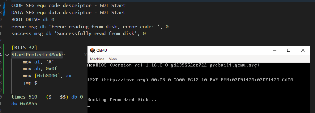
Because we entered protected mode, we can’t use the BIOS interrupts anymore. What I have done in the code is modify the VGA memory directly to print the letter ‘A’ on the screen. The VGA memory is located at 0xB8000.
The code is located at: github
Or here: pastebin
(maybe in the future I’ll change the github repo name)
Note: we must do far-jump, in this code:
jmp CODE_SEG:StartProtectedMode
There is something called CPU pipelining that runs instructions in parallel. Long story short, to force the CPU into the protected mode state we do a far jump. A far jump is a jump that changes the code segment and the instruction pointer. The CPU will not run the next instruction until the far jump is completed (if we don’t do this then the next instruction might be executed in 16-bit mode and not in 32-bit mode).
Orginize code into multiple ASM files
The code becomes messy. If its not clear yet, the best way to code is to split the code into multiple files. We will split the code into:
bootsector.asm - the first sector that will be loaded by the BIOS
gdt.asm - the code that will define the GDT
bios.asm - helper functions such as print string, print hex, and more
pm.asm - everything to do with entering protected mode
Then we use it in bootsector.asm:
Start:
    ...
    jmp EnterProtectedMode
...
%include "pm.asm"
%include "gdt.asm"
%include "bios.asm"
...
times 510 - ($ - $$) db 0
dw 0xAA55
Cross-Compiler
We will compile a cross-compiler for our OS. A cross-compiler is a compiler that runs on one platform/architecture but generates code for another platform/architecture. For example, I am running MacBook Pro M1 which isn’t running x86_64 but will output x86_64 code.
But even if you are running an x86_64 machine, it is still recommended to use a cross-compiler because it will be easier to compile the code for the OS. We will also force it to be specifically for our OS.
The best resource on how to create a cross-compiler is from: osdev.org
And also here: YouTube NanoByte
On macOS M1 chip
We can’t use the gcc and ld of the system because they are not GNU, which have specific features that we need (they are darwin - apple created them).
There is no way to avoid this but we must compile from source code to create our own compiler. First we install build dependencies:
brew install wget bison flex gmp libmpc mpfr texinfo mtools qemu nasm
Then we get binutils source from here. I chose binutils 2.40.
And we get gcc source from here. I chose gcc 12.2.0.
Put both the binutils and gcc into a folder in Desktop for example and extract:
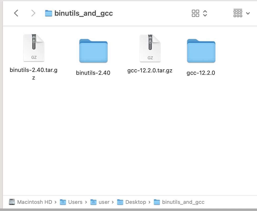
Now create build folder for gcc and build folder to binutils, call them build-gcc and build-binutils.
Before continuing, please read on osdev.org on how to build the cross-compiler.
Now lets cd into the directory where we extracted binutils and gcc. Lets set the environment variables:
export PREFIX="$HOME/Desktop/my_tools"
export TARGET=i686-elf
export PATH="$PREFIX/bin:$PATH"
Where prefix is the folder where we want to install the cross-compiler (the binaries). I don’t want to mess with my system utils so I created dedicated directory for binutils. target is the target architecture. We will compile for x64 and not x86 since we can compile 32bit on 64bit compiler anyways. And path is the path to the cross-compiler.
Now I cd into build-binutils and run: ../binutils-2.40/configure --target=$TARGET --prefix="$PREFIX" --with-sysroot --disable-nls --disable-werror
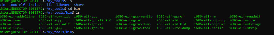
Now I run: make and after it finishes: make install:
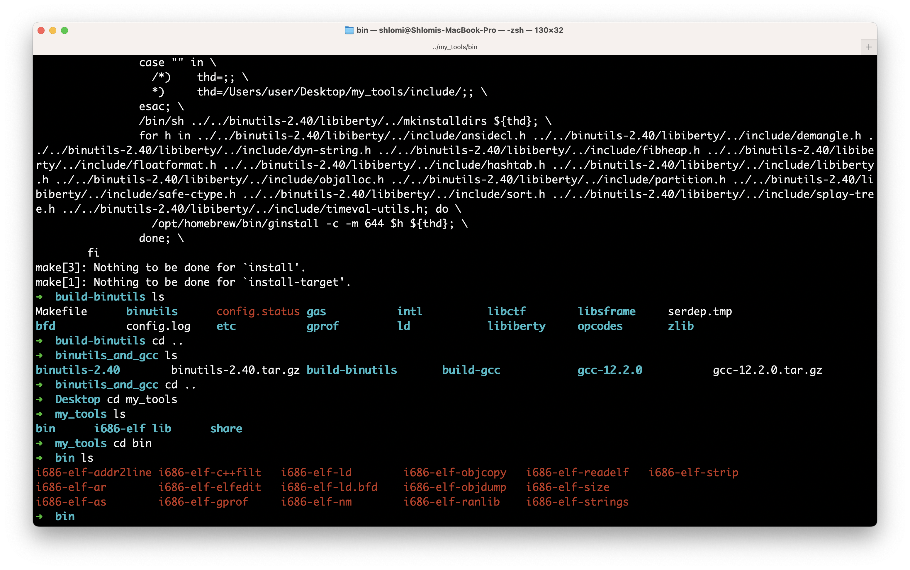
As we can see we compiled the binutils, which includes the linker i686-elf-ld.
Now to compile gcc:
cd binutils_and_gcc
cd build-gcc
../gcc-12.2.0/configure --target=$TARGET --prefix="$PREFIX" --disable-nls --enable-languages=c,c++ --without-headers
make all-gcc
make all-target-libgcc
make install-gcc
make install-target-libgcc
After I ran ../gcc-12.2.0 ...... it told me I’m missing packages:
configure: error: Building GCC requires GMP 4.2+, MPFR 3.1.0+ and MPC 0.8.0+.
Try the --with-gmp, --with-mpfr and/or --with-mpc options to specify
their locations.  Source code for these libraries can be found at
their respective hosting sites as well as at
https://gcc.gnu.org/pub/gcc/infrastructure/.  See also
http://gcc.gnu.org/install/prerequisites.html for additional info.  If
you obtained GMP, MPFR and/or MPC from a vendor distribution package,
make sure that you have installed both the libraries and the header
files.  They may be located in separate packages.
So I ran: brew install gmp mpfr mpc
But it didn’t fix that. After googling I ran the following command inside gcc directory: ./contrib/download_prerequisites and it fixed my problems, I ran ../gcc-12.2.0/configure --target=$TARGET --prefix="$PREFIX" --disable-nls --enable-languages=c,c++ --without-headers again.
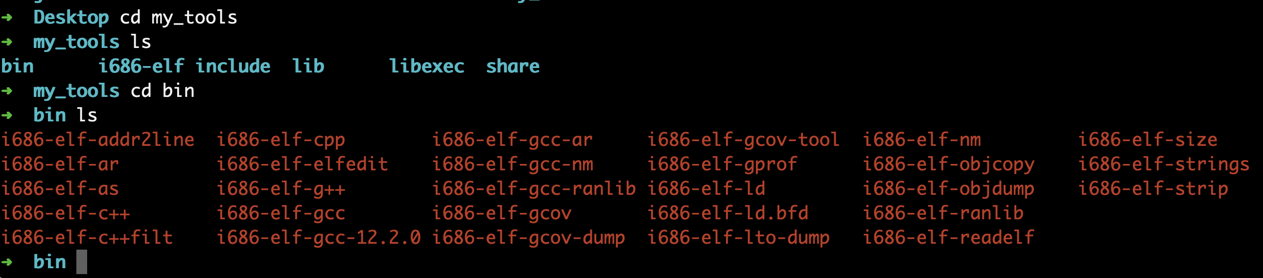
Now I ran make all-gcc and it worked. I continue to run the commands above.
Now gcc is installed aswell:
On Windows
On Windows we can download the source: here: binutils-2.40.tar.gz and here: gcc-12.2.0.tar.gz.
I am using WSL and we do everything simillar to macOS build (except we are using apt instead of brew to install dependencies):
sudo apt update && sudo apt upgrade
sudo apt install build-essential bison flex libgmp3-dev libmpc-dev libmpfr-dev texinfo mtools nasm wget
cd $HOME
mkdir binutils_and_gcc
cd binutils_and_gcc
mkdir build-binutils
mkdir build-gcc
wget https://ftp.gnu.org/gnu/binutils/binutils-2.40.tar.xz
wget https://ftp.gnu.org/gnu/gcc/gcc-12.2.0/gcc-12.2.0.tar.gz
tar -xf binutils-2.40.tar.xz
tar -xf gcc-12.2.0.tar.gz
mkdir $HOME/my_tools
export PREFIX="$HOME/my_tools"
export TARGET=i686-elf
export PATH="$PREFIX/bin:$PATH"
cd build-binutils/
../binutils-2.40/configure --target=$TARGET --prefix="$PREFIX" --with-sysroot --disable-nls --disable-werror
make
make install
cd ../build-gcc/
../gcc-12.2.0/configure --target=$TARGET --prefix="$PREFIX" --disable-nls --enable-languages=c,c++ --without-headers
make all-gcc
make all-target-libgcc
make install-gcc
make install-target-libgcc
Final result:
Writing our kernel
Now we write our kernel in C:
kernel.cpp:
extern "C" void main() {
	// Print OK on the next line
	*(char*)0xb8140 = 'O';
	*(char*)0xb8142 = 'K';
}
The reason we need to define “extern C” is because C++ mangles the function names (scrambles) and this prevents the compiler from mangling the function name (read about mangling on the internet its interesting).
We also need to call that function main from assembly:
kernel_entry.asm:
[BITS 32]
[extern main]

call main
cli
hlt
Compiling bootloader + kernel
Now we compile our kernel. We will use Makefile to orginize commands:
Makefile:
gnu_gcc := "/Users/user/Desktop/my_tools/bin/i686-elf-gcc"
gnu_ld := "/Users/user/Desktop/my_tools/bin/i686-elf-ld"

all:
# kernel.o
	$(gnu_gcc) -ffreestanding -m32 -g -c "kernel.cpp" -o "kernel.o"
# kernel_entry.o
	nasm "kernel_entry.asm" -f elf -o "kernel_entry.o"
# kernel.bin - link kernel_entry.o and kernel.o
	$(gnu_ld) -o "full_kernel.bin" -Ttext 0x1000 "kernel_entry.o" "kernel.o" --oformat binary
# boot.bin - bootloader
	nasm "bootsector.asm" -f bin -o "boot.bin"
# everything.bin - bootloader + kernel
	cat "boot.bin" "full_kernel.bin" > "everything.bin"
# zeroes.bin - zeroes
	nasm "zeroes.asm" -f bin -o "zeroes.bin"
# os.bin - everything + zeroes
	cat "everything.bin" "zeroes.bin" > "os.bin"
# run
	qemu-system-x86_64 -drive format=raw,file="os.bin",index=0,if=floppy,  -m 128M
The basic takeaway is this:
- First command: compile
kernel.cpptokernel.o - Second command: compile
kernel_entry.asmtoelffile and not bin, since we need to use linker and link theextern mainto resolve the symbol. - Third command: link
kernel_entry.oandkernel.otofull_kernel.bin- this is symbol resolving - Fourth command: compile
bootsector.asmto binary- The
nasmcompiler also compiles included assembly files, such asbios.asmandgdt.asm
- The
- Fifth command: the
catcommand concatinatesboot.binandfull_kernel.bintoeverything.bin. Basically we add the kernel sector next to the boot sector. - Sixth command: compile the
zeroes.asmfile to binary. We will use this to fill the rest of the floppy disk with zeroes.- Reason: we don’t know the size of the kernel. For now, we are reading 20 sectors of kernel in the bootloader. This is to allow the kernel binary to expand, untill it reaches 20*512=10MB in size. This is a plaster solution, but it works for now. We want something working first.
- Seventh command: concatinates
everything.binandzeroes.bintoos.bin. This is our final binary. Basically the boot loader won’t fail when reading 20 kernel sectors. - Eighth command: run
os.binin qemu.
My working code
kernel.cpp:
extern "C" void main() {
	// Print OK on the next line
	*(char*)0xb8140 = 'O';
	*(char*)0xb8142 = 'K';
}
kernel_entry.asm:
[BITS 32]
[extern main]

call main
cli
hltbootsector.asm:
[global Start]
[BITS 16]
[ORG 0x7C00]

section .text

Start:
    ; DL stores the current drive number, save in variable
    mov [BOOT_DRIVE], dl

    ; Initialize the stack
    mov bp, 0x7C00
    mov sp, bp

    call ClearScreen

    mov SI, hello_msg
    call PrintString
    call PrintNewLine

    ; Read kernel
    xor ax, ax
    mov es, ax
    mov ds, ax

    mov bx, KERNEL_ADDRESS
    mov dh, 20
    mov ah, 2
    mov al, dh
    mov ch, 0
    mov dh, 0
    mov cl, 2
    mov dl, [BOOT_DRIVE]
    int 0x13
    jc DiskError
    jmp NoDiskError

    DiskError:
        mov SI, disk_error_msg
        call PrintString

        ; Error code
        mov al, ah
        mov ah, 0
        call Print2Hex

        cli
        hlt
    NoDiskError:
        jmp EnterProtectedMode

%include "pm.asm"
%include "gdt.asm"
%include "bios.asm"


BOOT_DRIVE db 0
KERNEL_ADDRESS equ 0x1000 ; Don't start at 0 to avoid overwriting interrupt vector table of the BIOS
hello_msg db "Running in 16-bit real mode...", 0
disk_error_msg db "Error reading disk, error code: ", 0

times 510 - ($ - $$) db 0
dw 0xAA55pm.asm:
EnterProtectedMode:
    mov si, enter_pm_msg
    call PrintString
    call PrintNewLine

    ; Enter protected mode
    cli
    lgdt [GDT_Descriptor] ; Load GDT
    mov eax, cr0
    or eax, 0x1 ; Set protected mode bit
    mov cr0, eax
    jmp CODE_SEG:StartProtectedMode ; Far jump to code segment in protected mode, force CPU to flush pipeline
[BITS 32]
StartProtectedMode:
    ; Initialize segment registers immediately after entering protected mode
    mov ax, DATA_SEG
    mov ds, ax
    mov ss, ax
    mov es, ax
    mov fs, ax
    mov gs, ax

    ; Initialize the stack
    mov ebp, 0x90000
    mov esp, ebp

    ; TODO: Remove this 'OK' we do this in kernel in C++ instead
    ; Print 'OK' on second line (VGA memory starts at 0xB8000)
    ; mov al, 'O'
    ; mov ah, 0x0f
    ; mov [0xb80A0], ax
    ; mov al, 'K'
    ; mov [0xb80A2], ax

    ; cli
    ; hlt
    jmp KERNEL_ADDRESS

enter_pm_msg db "Entering protected mode...", 0gdt.asm:
GDT_Start:          ; Create a global descriptor table
    null_descriptor:
        dd 0x0 ; 8 bits of zeros
        dd 0x0
    code_descriptor:
        dw 0xFFFF ; Limit (16 bits)
        dw 0x0 ; Base (24 bits in total) (16 bits)
        db 0x0 ; Base (8 bits)
        db 10011010b ; First 4 bits: present, priviledge, type. Last 4 bits: Type flags
        db 11001111b ; Other flags (4 bits) + Limit (4 bits)
        db 0x0 ; Base (8 bits)
    data_descriptor:
        dw 0xFFFF ; Limit (16 bits)
        dw 0x0 ; Base (24 bits in total) (16 bits)
        db 0x0 ; Base (8 bits)
        db 10010010b ; First 4 bits: present, priviledge, type. Last 4 bits: Type flags
        db 11001111b ; Other flags (4 bits) + Limit (4 bits)
        db 0x0 ; Base (8 bits)
GDT_End:
GDT_Descriptor:
    dw GDT_End - GDT_Start - 1 ; Size of GDT
    dd GDT_Start ; Start address of GDT
CODE_SEG equ code_descriptor - GDT_Start
DATA_SEG equ data_descriptor - GDT_Startbios.asm:
[BITS 16]

Print4Hex:
    ; Input AX register, BL register (optional)
    ; Output: None
    ; Prints the hex value of AX register (4 nibbles). Example: AX=0x1234 will print: 0x1234
    ; If you want to print prefix '0x' then set BL=0, else set BL=1. Example: AX=0x1234, BL=1 will print: 1234
    push ax

    shr ax, 8
    mov ah, bl ; Print prefix according to BL input for first byte
    call Print2Hex

    ; Print low byte
    pop ax
    mov ah, 1 ; Here we don't need to print prefix
    call Print2Hex

    ret

Print2Hex:
    ; Input: AL register, AH register (optional)
    ; Output: None
    ; Print the hex value of AL register (2 nibbles). Example: AL=0x12 will print: 0x12
    ; If you want to print prefix '0x' then set AH=0, else set AH=1. Example: AL=0x12, AH=1 will print: 12
    cmp ah, 1
    je .no_prefix
    ; Print hex prefix
    push ax
    mov al, '0'
    call PrintCharacter
    mov al, 'x'
    call PrintCharacter
    pop ax ; Get the argument
    .no_prefix:

    ; Print high nibble
    call ALToHex
    push ax ; Store for low nibble printing later on
    mov al, ah ; Move high nibble to AL, since the PrintCharacter procedure expects the character in AL
    ; Check if nibble is greater than 0x9. If it does, then we need offset of 0x41 to get 'A' in ASCII. Else, we need offset of 0x30 to get '0' in ASCII.
    cmp al, 0xA
    jl .finish
    add al, 0x7
    .finish:
    add al, 0x30
    call PrintCharacter

    ; Print low nibble
    pop ax
    cmp al, 0xA
    jl .finish2
    add al, 0x7
    .finish2:
    add al, 0x30
    call PrintCharacter

    ret

ALToHex:
    ; Input: AL register
    ; Output: AX register
    ; Convert a number in AL to hex nibbles. Example: 256 -> 0xAB. The high nibble (0xA) is stored in AH and the low nibble (0xB) in AL
    push ax ; Save AL
    ; Get high nibble of AL, store in DH for later retrieval
    and al, 0xF0
    shr al, 4
    mov dh, al

    pop ax
    ; Get low nibble of AL, store in AL
    and al, 0x0F

    mov ah, dh ; Retrieve high nibble from DH to AH
    ret
PrintCharacter:                         ;Procedure to print character on screen
                                        ;Assume that ASCII value is in register AL
    mov ah, 0x0E                        ;Tell BIOS that we need to print one charater on screen.
    mov bh, 0x00                        ;Page no.
    mov bl, 0x07                        ;Text attribute 0x07 is lightgrey font on black background
    int 0x10                            ;Call video interrupt
    ret                                 ;Return to calling procedure
PrintString:                            ;Procedure to print string on screen
                                        ;Assume that string starting pointer is in register SI
    .next_character:                     ;Lable to fetch next character from string
        mov al, [SI]                    ;Get a byte from string and store in AL register
        inc SI                          ;Increment SI pointer
        or AL, AL                       ;Check if value in AL is zero (end of string)
        jz .exit_function                ;If end then return
        call PrintCharacter             ;Else print the character which is in AL register
        jmp .next_character              ;Fetch next character from string
        .exit_function:                  ;End label
        ret                             ;Return from procedure
PrintNewLine:
    ; Print new line
    mov al, 0x0D
    call PrintCharacter
    mov al, 0x0A
    call PrintCharacter
    ret
ClearScreen:
    mov ah, 0x0
    mov al, 0x3
    int 0x10
    ret
DiskErrorMessage db "Error reading disk, error code: ", 0zero.asm:
times 10240 db 0And the makefile is mentioned in the section above.
Final result
